
A 1-wire Temp Implementation
This isn't intended to be instructions for 1-wire. Instead, it's intended to describe the way to put 1-wire temp sensors around your house.
I started with humidity sensors in the crawl space, using the iButtonlink Temperature and Humidity Multisensor. A great piece of hardware, but for my purposes it had four flaws: It uses Cat5, it's expensive to deploy lots of them, it requires two separate wires, and most importantly from my wife's perspective, it's bright yellow.
1-wire had an additional problem - it's serial, and I wanted an easy way to not treat it that way. Here's what I wanted my implementation to look like to the end user:

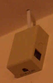
The end result looks something like this:
The plan was to use 4-wire telephone cord to serve as both the "in" and "out" side of the 1-wire, so I could connect to a device using a single RJ11 connection, and then join things up along the backbone. Red and Green are the line coming "in", and Black and Yellow will be the line coming "out", making one length of phone cord the line both to and from the sensor.
For each sensor I purchased:
$6.76 DS1920-F5+ 1-wire DS1920 iButtons from Dallas. (They're cheaper
from www.ibuttonlink.com
at $4.25, especially after shipping)
$2.34 DS9094FS+
iButton clip
$1.95 Surface
modular phone jack from Radio Shack
$2.00 RJ11 Telephone Jack 3 Way
Splitter from abccables.com
$1.00 RJ11 Data Coupler
from abccables.com
Total cost for a sensor: $9.59 (+ shipping of course). I bought enough for 5 of them. That's not counting the cost for the cable (old phone lines I had around the house) and RJ11 connectors. I already had the crimper for making cables.
Instructions:
First, open up the modular phone jack:
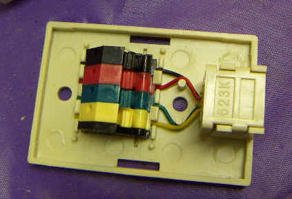
Pried out the contacts:
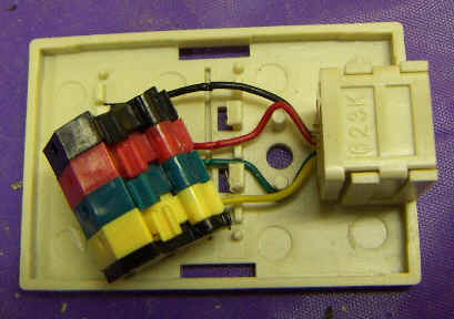
And cleaned up the wiring:
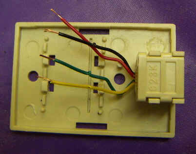
Next I stuck on a dab of hot glue (note the wiring here should be GB, RY,
not GY, RB as indicated - oops) 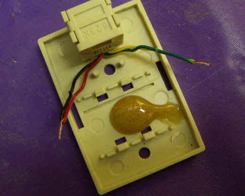
and glued the iButton clip in place. Note your life will be a lot easier if you set the clip facing the same way in all of them. If some are to the left and some are to the right, it's harder to remember which side is "ground".
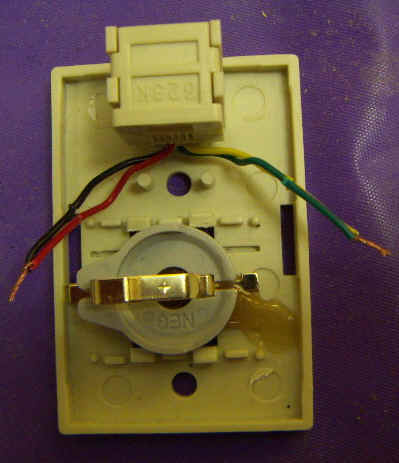
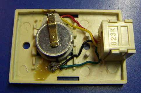
And solder the wiring in place, and insert the iButton: (this one with the wiring correct)
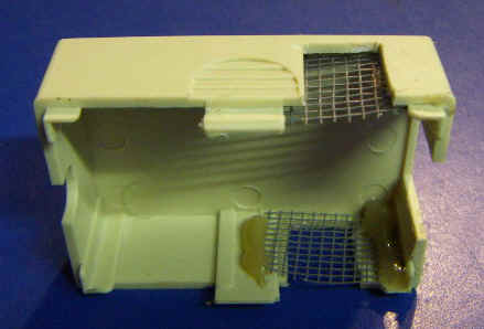
Next, I took the cover and cut air holes in it with a Dremel, and glued mesh in place:
The whole thing assembled looks like this:

So a two wire line comes "in" on RG with the 1-wire signal to the data coupler. the signal then passes through the the splitter as L1. The signal travels over a four-wire cable connected to L1+L2 on RG to the sensor, and comes back out on BY on L2. A two wire RG phone cable runs from L2 to the next sensor array's data coupler. The line between the splitter and the sensor has all four wires, being both the in and the out. The coupler line and L2 line are just RG. Because of the cables crossing over, you have to be sure you get the cables correct. You clearly won't hurt anything if you get it wrong, except that no sensors will be reported on the line.
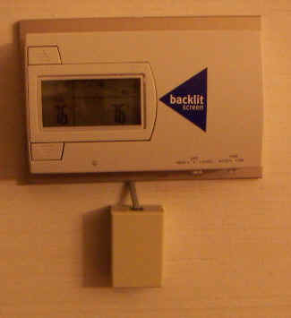
You can make this sensor wire whatever length you need to have the sensor mounted on the wall. Here's another one set next to the thermostat. All of the connectors are in the wall.
The end result gives me exactly what I wanted. Hope that's helpful to someone.